Introduction to Digital Multimeters - Part 2
Introduction to Digital Multimeters - Part 2
September 16th, 2020:
In our Introduction to Digital Multimeters - Part 1 we discussed the different types of multimeters as well as many of their basic features. This time we will jump right in to show how these meters are used to make different types of measurements.
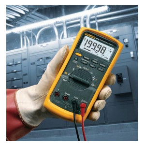
AC and DC Voltage
One of the most basic tasks of a DMM (digital multimeter) is measuring voltage. A typical DC voltage source is a battery, like the one used in your car. AC voltage is usually created by a generator. The wall outlets in your home are common sources of AC voltage. Some devices can actually convert AC voltage to DC voltage. For example, electronic equipment such as TVs, stereos and computers that you plug into an AC wall outlet use devices called rectifiers to convert the AC voltage to a DC voltage signal, which powers the electronic circuits in those devices.
Testing for proper supply voltage is usually the first step when troubleshooting a circuit. If there is no voltage present, or if it is too high or too low, the voltage problem should be corrected before investigating further.
The waveforms associated with AC voltages are either sinusoidal (sine waves) or non-sinusoidal (sawtooth, square, ripple, etc.). Good quality DMMs display the "RMS" (root mean square) value of these voltage waveforms. The RMS value is the effective or equivalent DC value of the AC voltage.

Most DMMs are "average responding", giving accurate RMS readings if the AC voltage signal is a pure sine wave. Average responding meters are not capable of measuring non-sinusoidal signals accurately. Mom-sinusoidal signals are accurately measured using DMMs designated as "True-RMS" up to the DMM's specified crest factor. Crest factor is the ratio of a signal's peak-to-RMS value. It's 1.414 for a pure sine wave, but is often much higher for a rectifier current pulse, for example. As a result, an average responding meter will often read much lower than the actual RMS value.
A DMM's ability to measure AC voltage can be limited by the frequency of the signal. Most DMMs can accurately measure AC voltages with frequencies from 50 Hz to 500 Hz, but a DMM's AC measurement bandwidth may be hundreds of kilohertz wide. Such a meter may read a higher value because it is "seeing" more of a complex AC signal. DMM accuracy specifications for AC voltage and AC current should state the frequency range along with the range's accuracy.
How to make voltage measurements:
- Select AC voltage or DC voltage as desired.
- Plug the black test probe into the COM jack. Plug the red test probe into the V input jack.
- If the DMM has manual ranging only, select the highest range so as not to overload the input.
- Touch the probe tips to the circuit across a load or power source (in parallel to the circuit).
- View the reading, being sure to note the unit of measurement.
NOTE: For DC readings of the correct polarity (+/-), touch the red test probe to the positive side of the circuit and the black probe to the negative side or circuit ground. If you reverse the connections, a DMM with auto-polarity will merely display a minus (-) sign, indicating negative polarity. With an analog meter, you can risk damaging the meter.
NOTE: 1/1000V = 1 mV and 1000V = 1 kV. High-voltage probes are available where voltages can reach upwards of 40 kV.
HOWEVER - CAUTION: These probes are NOT intended for electrical utility applications in which high voltage is also accompanied by high energy. Rather, they are intended for use in low-energy applications.
AC and DC Current
Current measurements are different from other DMM measurements. Current measurements taken with the DMM alone require placing the meter in series with the circuit being measured. This means opening the circuit and using the DMM test leads to complete the circuit. This way all the circuit current flows through the DMM's circuitry. Or, an indirect method of measuring current on a DMM can be performed using a current probe. The probe clamps around the outside of the conductor, thus avoiding opening the circuit.
How to make current measurements:
- Turn off power to the circuit.
- Cut or unsolder the circuit, creating a place where the meter probes can be inserted.
- Select AC current or DC current as desired.
- Plug the black test probe into the COM input jack. Plug the red test probe into the amp or milliamp input jack, depending on the expected value of the reading.
- Connect the probe tips to the circuit across the break so that all current will flow through the DMM (a series connection).
- Turn the circuit power back on.
- View the reading, being sure to note the unit of measurement.
Resistance
Resistance is measured in ohms (Ω). Resistance values can vary greatly, from a few milliohms (mΩ) for contact resistance to billions of ohms for insulators. However, most DMMs measure down to 0.1Ω and some measure as high as 300 MΩ (300,000,000 ohms). Infinite resistance (open circuit) is read as "OL" on most meter displays, meaning the resistance is greater than the meter can measure.
Resistance measurements must be made with the circuit power off. Otherwise the meter or circuit could be damaged. Some DMMs provide protection in the ohms mode in case of accidental contact with voltages. The level of protection may vary greatly among different DMM makes and models.
For accurate, low-resistance measurements, resistance in the test leads must be subtracted from the total resistance measured. Typical test lead resistance is between 0.2Ω and 0.5Ω. If the resistance in the test leads is greater than 1Ω, the test leads should be replaced.
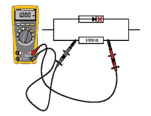
If the DMM supplies less than 0.6 DCV test voltage for measuring resistance, it will be able to measure the values of resistors that are isolated in a circuit by diodes or semiconductor junctions. This often allows you to test resistors on a circuit board without unsoldering them (see below).
How to make resistance measurements:
- Turn off power to the circuit.
- Select Resistance (Ω).
- Plug the black test probe into the COM input jack. Plug the red test probe into the Ω input jack.
- Connect the probe tips across the component or portion of the circuit for which you want to determine resistance.
- View the reading, being sure to note the unit of measurement - Ohms (Ω), Kilohms (kΩ) or Megohms (MΩ).
NOTE: 1,000 Ω = 1 kΩ and 1,000,000 Ω = 1 MΩ. Make sure the power is off before making resistance measurements.
Continuity and Diode
Continuity is a quick go/no-go resistance test that distinguishes between an open and a closed circuit. A DMM with a continuity beeper allows you to complete many continuity tests easily and quickly. The meter beeps when it detects a closed circuit, so you don't have to look at the meter as you test. The level of resistance required to trigger the beeper varies depending on the make and model of DMM.
A Diode is like an electronic switch. It can be turned on if the voltage is over a certain level, generally about 0.6V for a silicon diode, and it allows current to flow in one direction. When checking the condition of a diode or transistor junction, an analog VOM not only gives widely varying readings but can drive currents up to 50 mA through the junction (see table below).

Some DMMs have a diode test mode. This mode measures and displays the actual voltage drop across a junction. A silicon junction should have a voltage drop less than 0.7V when applied in the forward direction and an open circuit when applied in the reverse direction.
If you missed Part 1, be sure to check out our Introduction to Digital Multimeters - Part 1
Note: Information taken from an application note courtesy of Fluke Electronics Corporation (which can be found HERE). Ram Meter Inc. sells and stocks an assortment of Fluke digital multimeters and other products, which can all be found on our website at www.rammeter.com/fluke-electronics